
Since the sunspot numbers are picking up and summer is on its way, I thought I would build an antenna for the high bands: 10m through 20m. It’ll pair nicely with the QMX that I have just begun building.
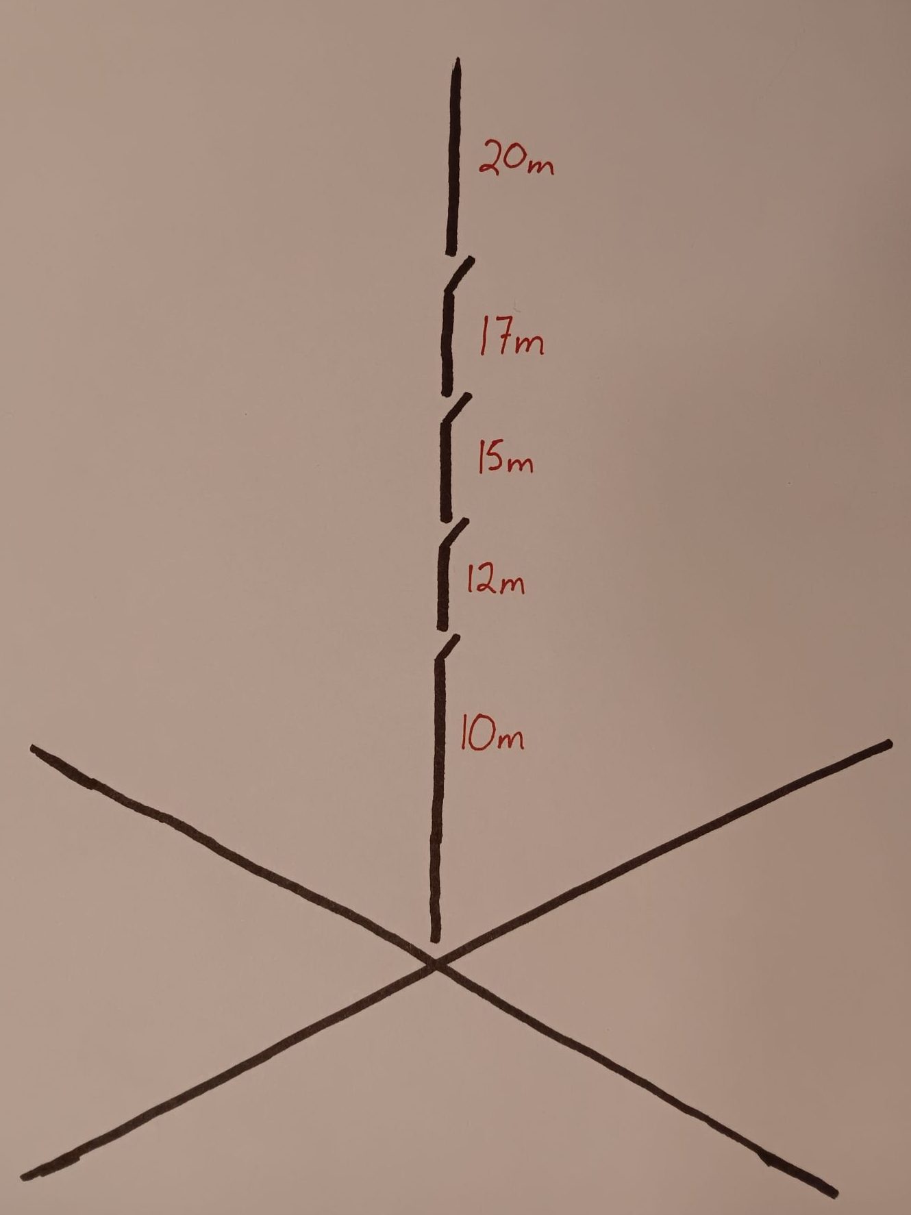
In short, I’ve built a vertical antenna for 10m, 12m, 15m, 17m, and 20m. This is accomplished through a series of links which create a resonant quarter wave for each desired band.
As a ground plane, I have put down sixteen 10ft radials. These radials come out to just over two wavelengths on 20m, the lowest band of operation for this antenna. This isn’t a random number of radials that I have landed upon. I’m standing upon the shoulders of Rudy Severn’s genius article (N6LF).
Building this antenna is easy and makes for a great first foray into antenna construction. In my opinion, it is also easier to tune and use in the field than a dipole is.
Below are the tools, materials, and a guide for how I made my vertical antenna.
Tools
- Measuring Tape
- 3x Tent Stakes and Mast – or – Throwline setup with at least 20 feet overhead
- Plastic Clip
- Crimpers
- Strippers
- Drill and Bits
- Soldering Iron
- Screwdriver
- Knife
- Heat Gun
- Antenna Tuner
Materials
- 180 to 200ft of Wire (I used 24 awg)
- 5x Ring Terminals (I used 16-22 awg)
- Heat Shrink
- 1x Female BNC Connector with Threads and Lock Nut
- 1x Bolt, 2x Nuts, and 1x Wingnut that fit your Ring Terminals (I used #6 hardware)
- 1x suitable piece of rigid, non-conductive material for the feedpoint. (Mine is roughly 1.5in by 3in.)
- 4x Alligator Clips with Screw
- 4x Female Spade Terminals (I used 16-22 awg)
- Solder
- Rope
- Small Bungee Cord, like a hair tie
Part One: Building the Ground Plane
Step One: Measure the radials
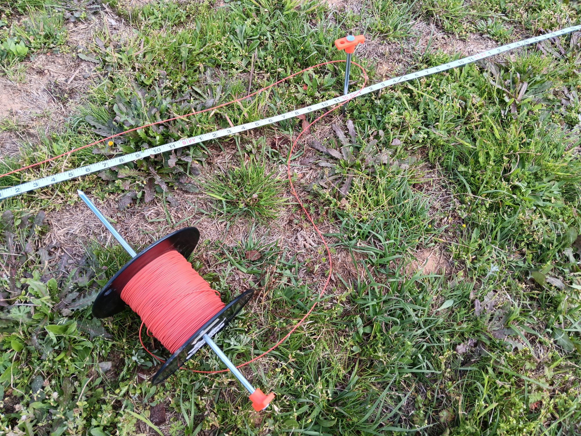
Since my radials are 10 feet each, I’ve taken my tape measure and placed a tent stake at 0 feet and at 10 feet. Then, I’ve taken my wire and clipped it at 0 feet.
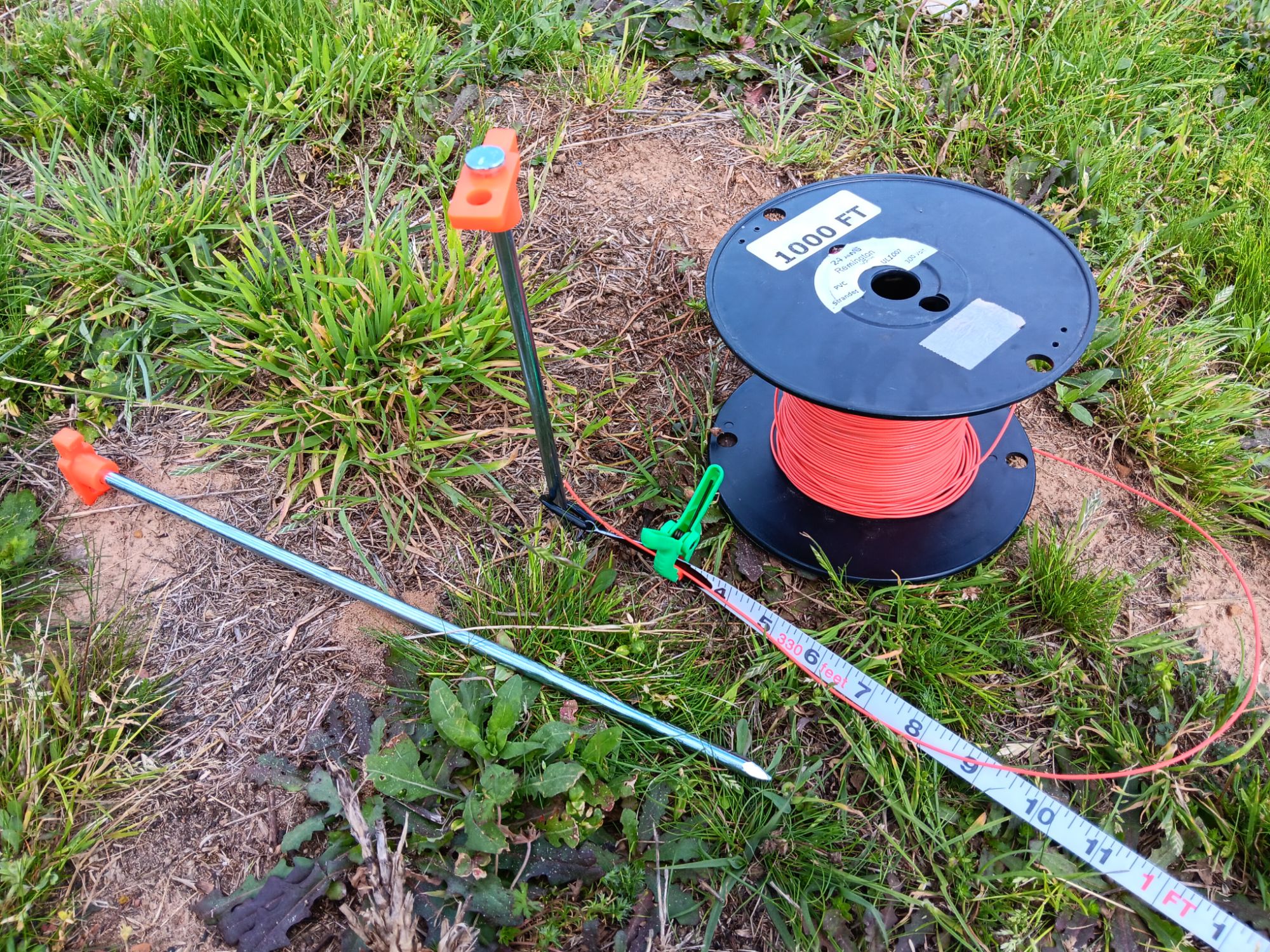
Next, I’ve taken my reel of wire and gone around my tent stakes eight times, giving me a total of 160 feet unspooled.
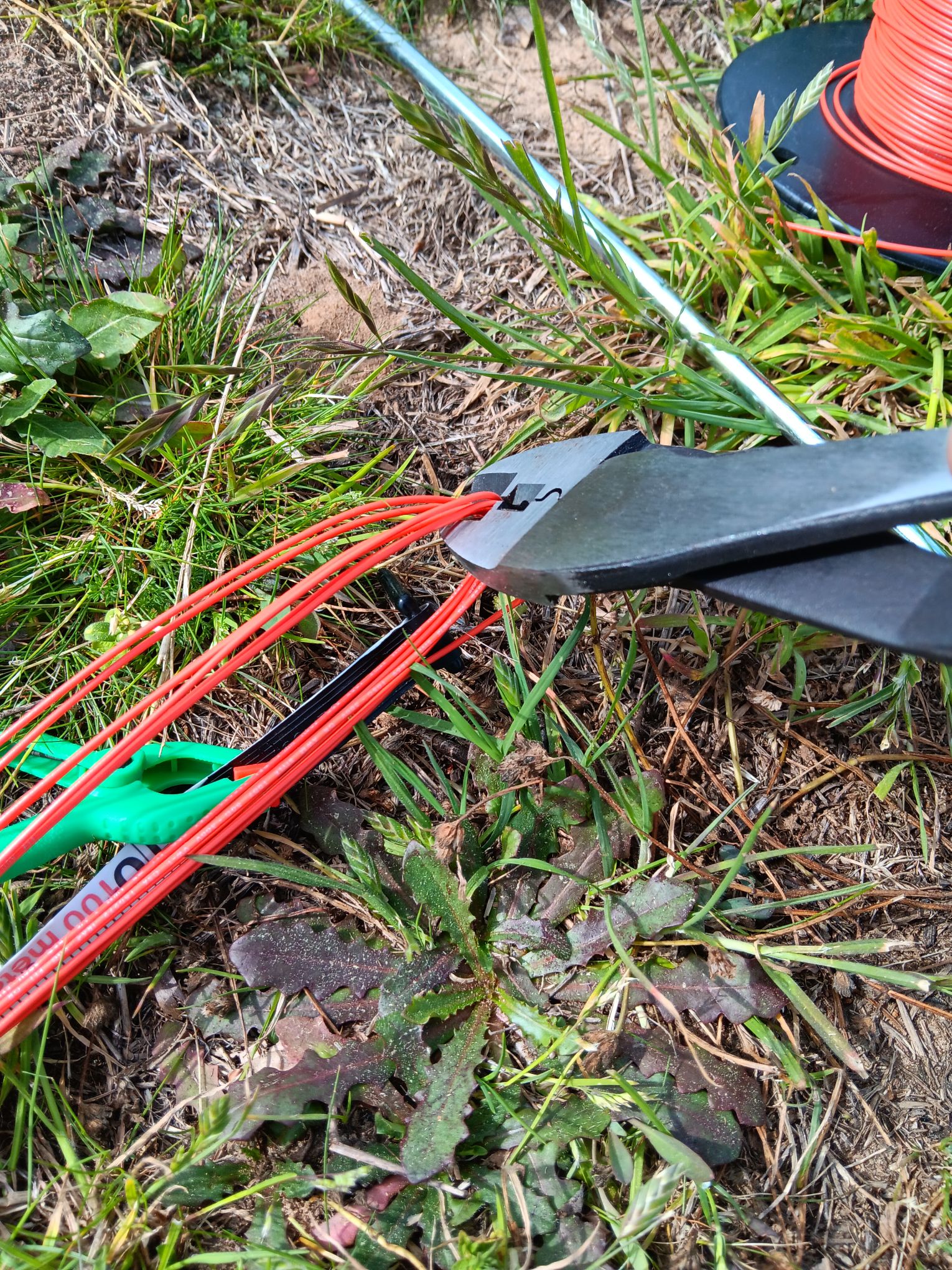
Step Two: Cutting them to length
Now, I’ve cut both ends of the loop. This gives me sixteen 10 foot pieces of wire.
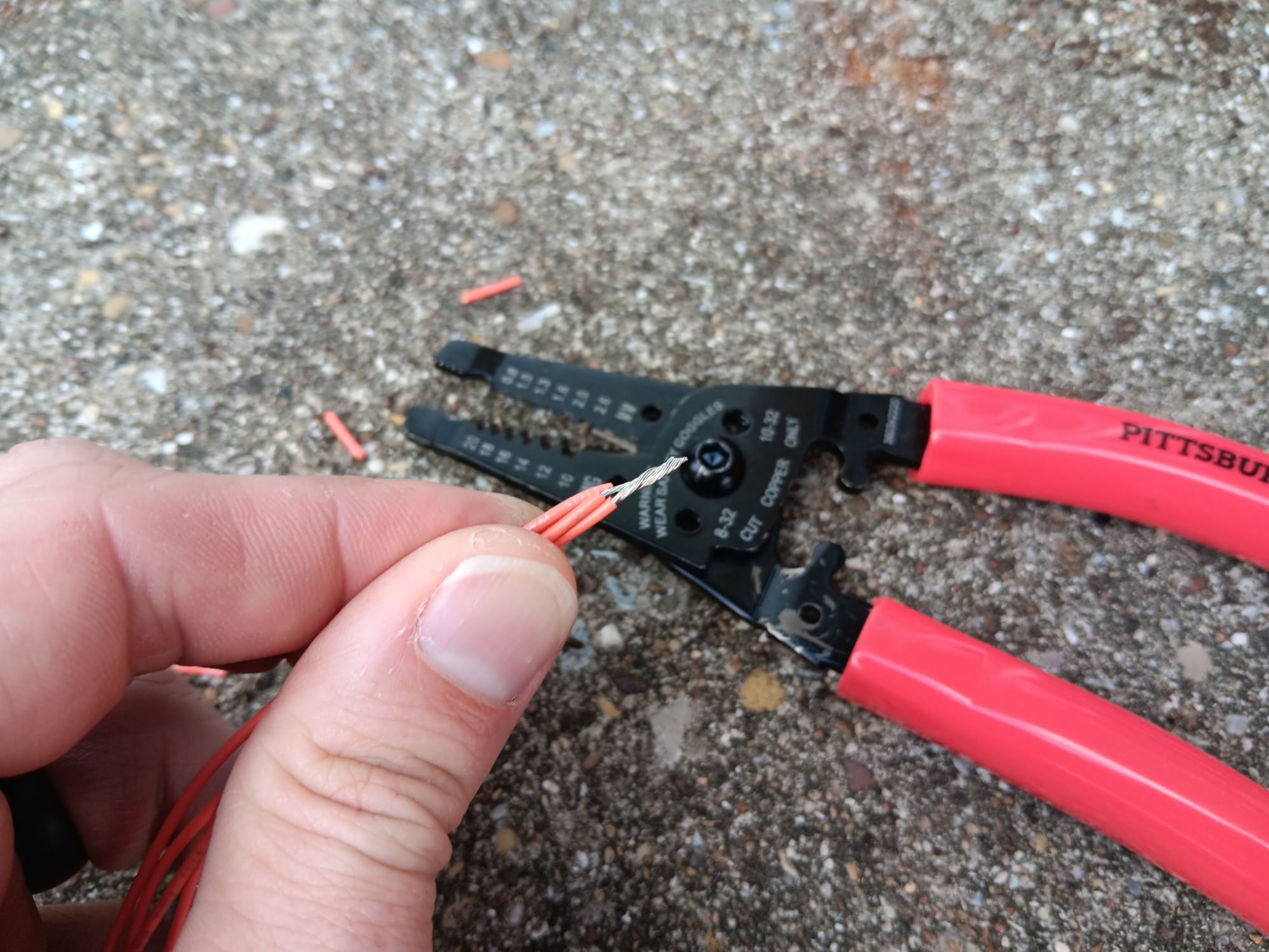
Step Three: Stripping the ends
Now that I have sixteen 10 foot pieces of wire, I strip one end of each wire and divide them into four groups of four.
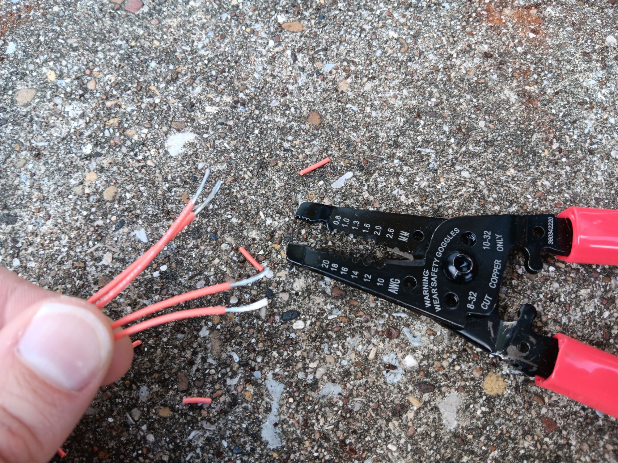
Step Four: Crimping the sets of four
Now that the wires are stripped, I twist the ends together.
Then I take a piece of heat shrink, slip it over the four wires, add a ring terminal, and crimp it into place. The ring terminal is sized 16-22 awg.
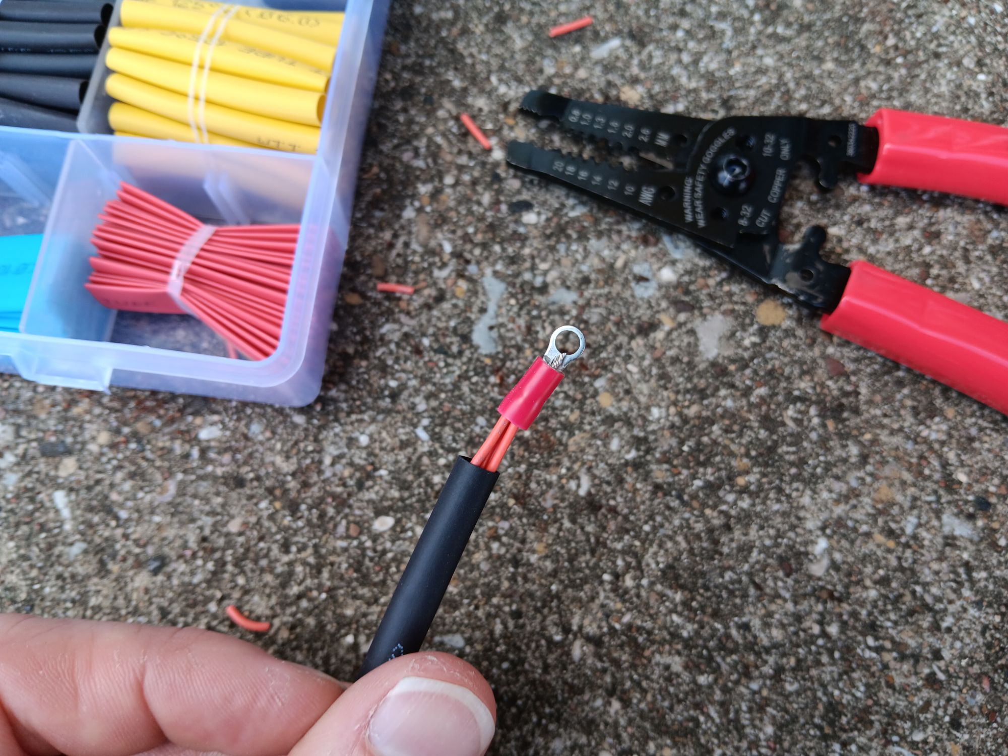
Repeating this step four times gives me four sets of four ground wires.

I will use the heat gun on the heat shrink after I’m done with tuning the antenna. That way, I can heat shrink everything all at once.
Part One Complete!
Part Two: Building the Feedpoint
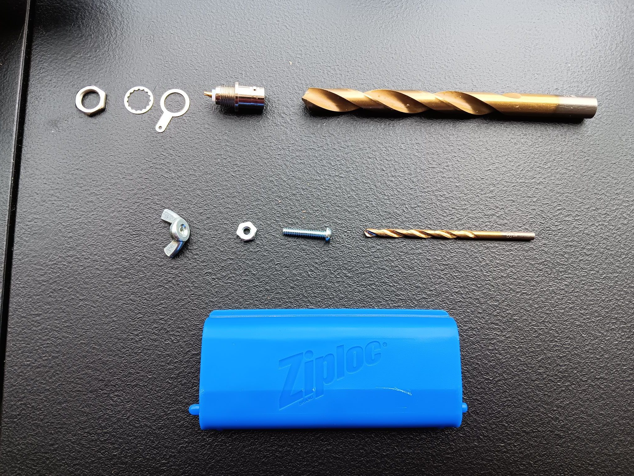
Step One: Gather the hardware and appropriately sized drill bits
For this step, I chose a 3/8 bit for the BNC connector hole and a 1/8 bit for the #6 bolt. Hold the bits up next to the hardware to ensure that they are the correct size.
Step Two: Drill the mounting holes into the feedpoint plate
As you can see, I have drilled one hole for the BNC connector, one hole for the ground plane mounting bolt, and two holes above the BNC connector hole. These two holes are for threading through the radiating element for some mechanical strength.

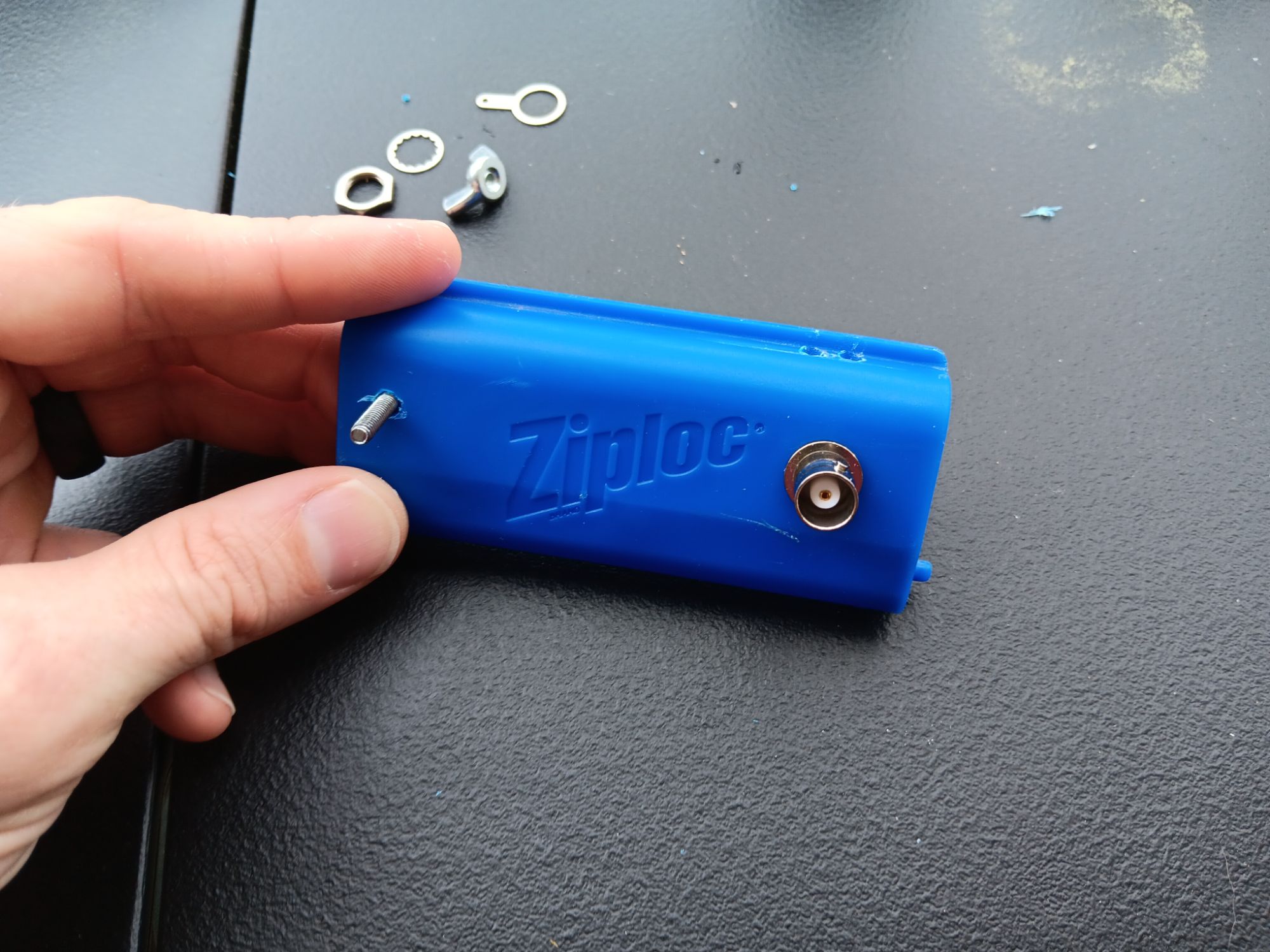
Make sure the hardware fits into the feedpoint plate before moving forward.
Step Three: Measure and cut the radiating element, then solder the radiating element to the BNC
Measure and cut a quarter wave radiating element for the highest band of operation. Since my highest band of operation is 10m, I have cut a piece of wire approximately 9 feet long.
234 / frequency of operation in MHz = length of quarter wave in feet
For 28.060 MHz, the formula gives me quarter wave of 8.339 feet, or 8 feet, 4 inches. I like to add a few extra inches because I like to have plenty of room for error.
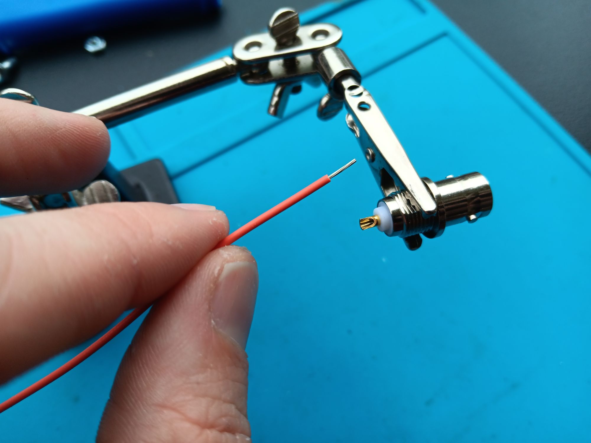
Next, strip back the wire enough to fit into the BNC.
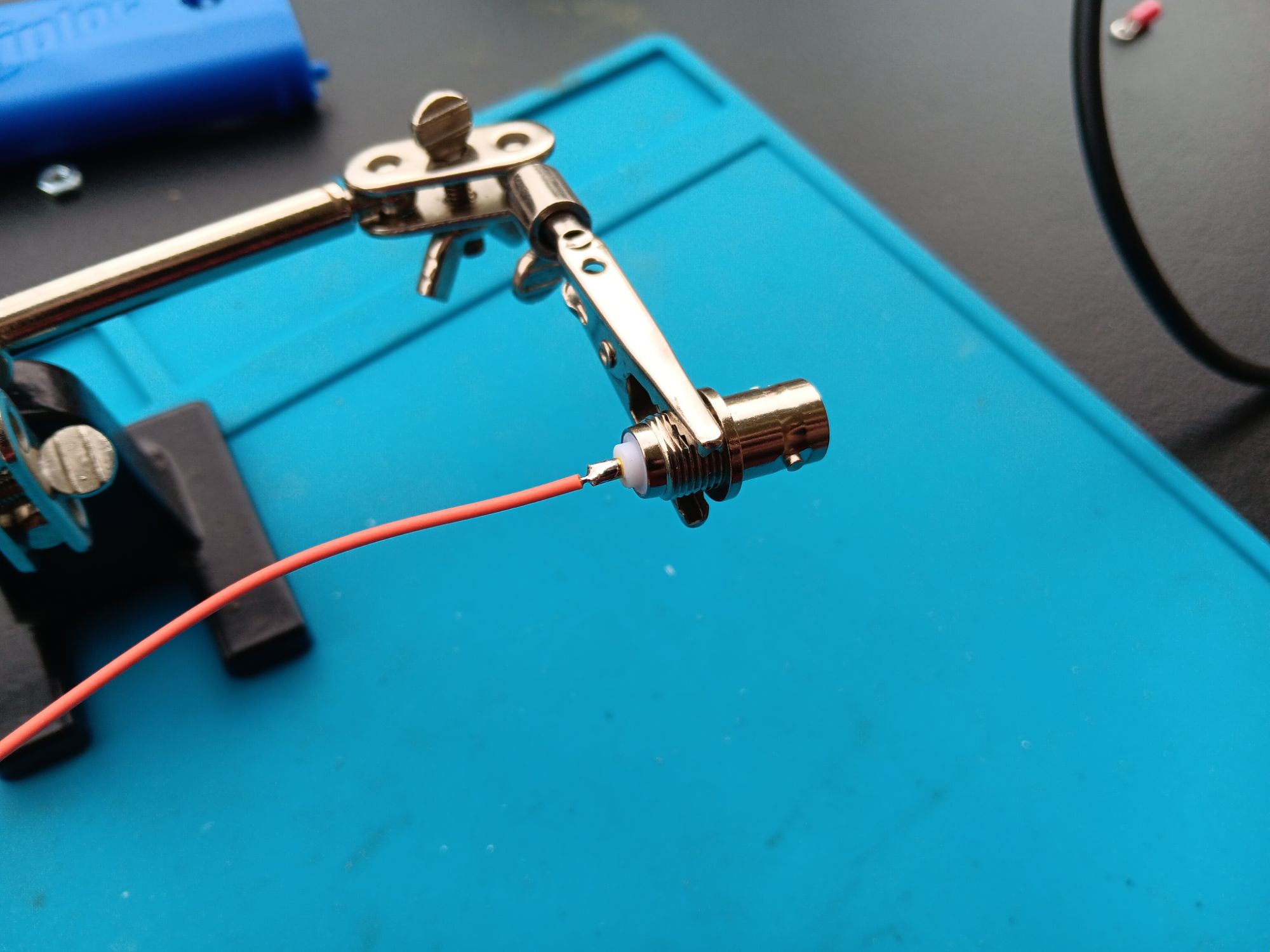
Then, solder it into place.
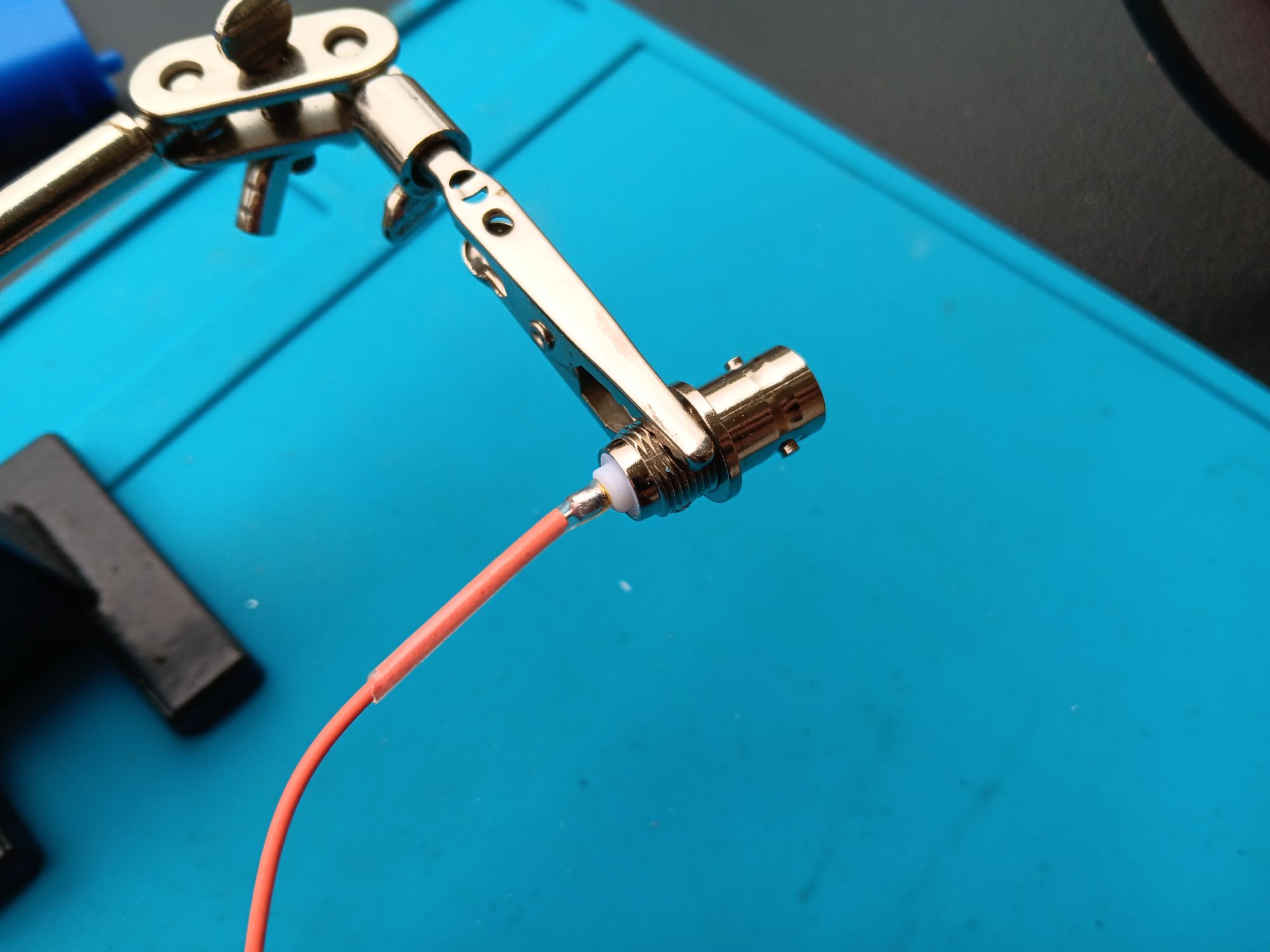
Here, I have applied some clear heat shrink to protect one of the most critical and delicate parts of the antenna.
Step Four: Solder a jumper wire to the BNC ground ring

Find a small piece of wire, some three or four inches in length. Strip it, insert it into the ring, then wrap the wire back onto itself for strength. Then, solder it. I’ve not added heat shrink here since there is little risk of moving, therefore damaging this part once installed.
Step Five: Install the BNC to the feedpoint plate
Here, I have demonstrated the order in which I have attached the BNC connector to the feedpoint plate.
Two things are important here: ensuring the ground ring has electrical continuity with the body of the BNC connector and that the BNC connector has a strong mechanical connection to the feedpoint plate.
Step Six: Attach ground jumper to ring terminal and ground plane bolt
Slip a ring terminal onto the ground plane bolt.
Next, cut and strip the ground jumper. Try to cut the ground jumper just long enough to reach completely through the ring terminal. The neater this is, the less chance of excess wire being caught on anything that can damage it.
After crimping the ring terminal to the ground jumper, I tighten a #6 nut against the feedpoint plate. Next, I have slipped the ring terminal onto the bolt, then I’ve added a second #6 nut onto the bolt. Tighten these well so that they do not want to rotate at all.


Part Seven: Thread the radiating element through the strain relief holes
Step Eight: Attach a bungee cord to the feedpoint plate
This step is not necessary, but I think it makes field setup easier on the coax and the radiating element if the feedpoint is secured to the mast.
It may be hard to tell from this photo, but the bungee cord is a hair tie. The loop goes underneath the ground jumper. The opposite side of the loop is then wrapped around the mast, then slipped over the feedpoint plate again next to the BNC.
Part Two Complete!
Part Three: Tuning the Radiator
Step One: Erect mast, attach feedpoint, ground radials, coax, and prepare radiating element
In order to tune the antenna, I chose an open spot behind our apartment. As you can see, the radials all slip on to the ground bolt, then are tightened down using a #6 wingnut. I’ve arranged them relatively evenly around the mast.
After attaching the feedpoint to the mast, I strung some thin rope through an eyelet that I’ve put on the top of my mast.

Next, I’ve slipped a plastic clip through a loop in the line.

Then, I’ve clipped the radiating element to the plastic clip. This allows me to make tuning much quicker since I don’t have to undo then retie a knot each time I make an adjustment to the antenna. After the radiating element is attached, I then erect the mast until the radiating element is taught.
Step Two A: Trim the element to resonance
According to my antenna analyzer, the element was resonant around 25 MHz, so way too long. This is good. It is easier to trim wire than reattach it. I kept trimming little by little until I achieved resonance on 28.060, a popular QRP frequency for 10m.
Step Two B: Attach a female spade connector

Now that the element is resonant, I have stripped the wire a little, slipped on a piece of heat shrink, and crimped a female spade connector on the resonant wire.
Step Two C: Cut new element and attach alligator clip
Now, I have cut a new piece of wire for my next resonant section. Since the first one was cut for 10m, this next piece will be for 12m.
To determine the length of wire for the next section, calculate the length of a resonant quarter wave, repeat the formula:
234 / frequency of operation in MHz = length of quarter wave in feet
234 / 24.906 MHz = 9.395 feet
For a frequency of 24.906 MHz, I get a length of 9.4 feet.
I then measured the actual length of wire on the antenna. It came out to 7.5 feet. I then subtract the existing 10m element from the 12m element I’m creating to get:
9.4 – 7.5 = 1.9 feet
Again, I like to add extra, so I cut my next section of wire 2.5 feet long.
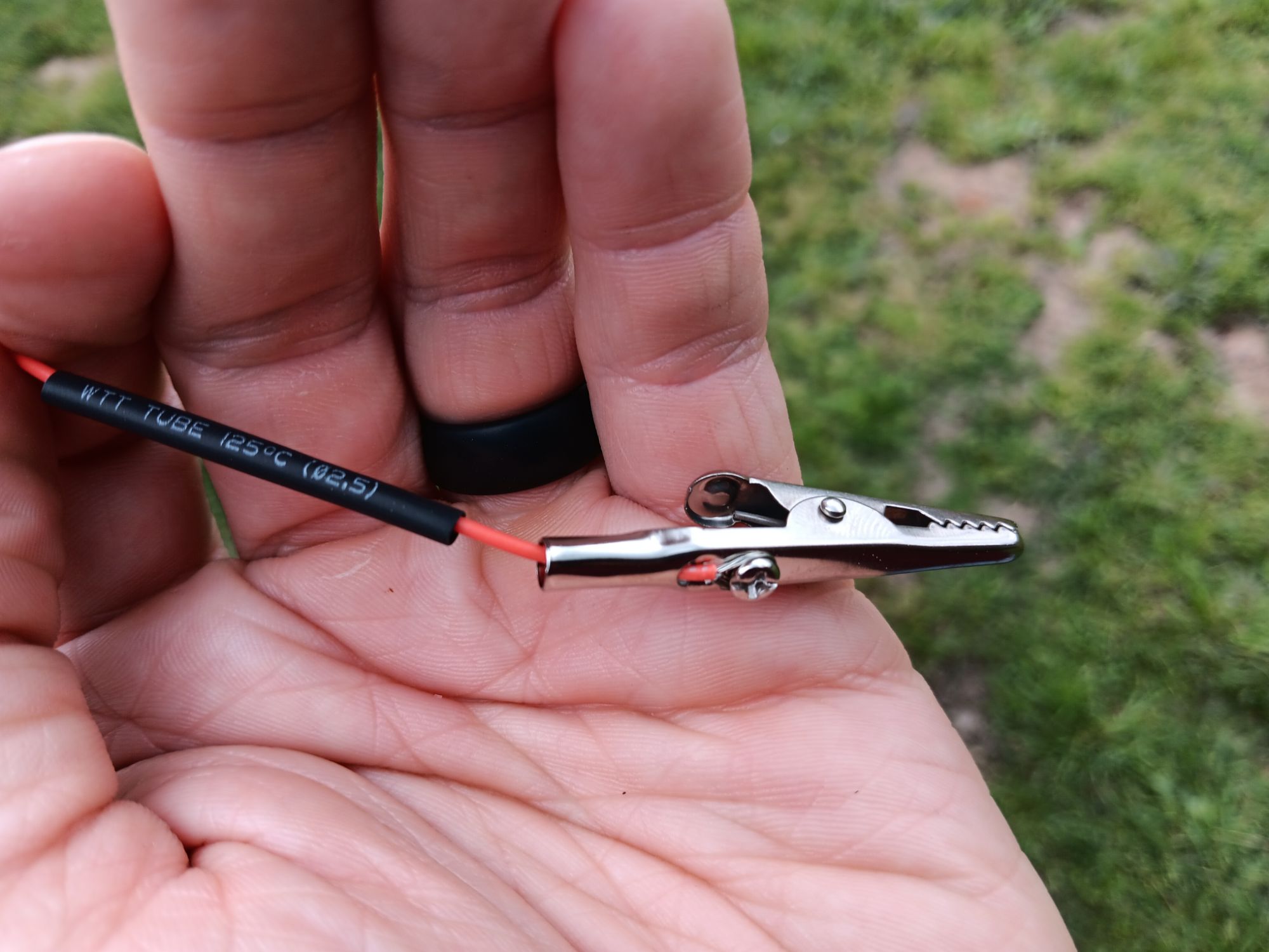
After cutting and stripping this new piece of wire, I thread it through the alligator clip and tighten the screw around the stripped wire.
Step Two D: Attach alligator clip to female spade connector

After the new section is attached to the existing radiator, I then clipped the end of the new section to the plastic clip on the rope and pulled the antenna taught.
I repeat Step Two, parts A through D, for all the bands I need. The steps are straightforward: trim the new element to resonance, crimp the spade connector, cut a new wire, attach a alligator clip to the new wire, clip the plastic clip to the top of the new wire, then repeat the tuning procedure. I did this procedure a total of four times, once for each link that I needed.
I hope that these instructions help you build your own linked vertical. Please add a comment with any questions or additions to the instructions you’d like to suggest.
Happy building and best of luck on the air!
