When building the 5Watter by W8DIZ, K7QO recommends building the power supply first as a troubleshooting measure. If the voltage regulators are installed and giving correct voltages, then you’ve eliminated one potential problem down the line. That, and it is difficult to determine whether everything else is working correctly if you can’t feed power to them.
Components
For this step, I will install the following:
- D12 – 1N5817 Schottky diode
- 12VDC power supply leads
- C49, C57 – 47uF electrolytic capacitor
- C38 – 10uF electrolytic capacitor
- U6 – 78L05 5V regulator
- U7 – 78L08 8V regulator
- C25, C29, C32, C39, C54, C55, C56 – 100nF monolithic capacitor
- R19 – 4.7k resistor
- R17 – 470 resistor
- D5 – 1N5240B 10V Zener diode
Circuit Explanation
Below is my attempt to explain why certain components are used.
Why is D12 (1N5817) a Schottky diode placed near the 12 VDC input? Schottky diodes are commonly used for providing reverse polarity protection. That still doesn’t answer the question though. A Schottky diode is placed here because it does reverse polarity protection quickly, has a small forward voltage drop, and has low capacitance for a diode. The downside is that if a high reverse polarity voltage is applied, the diode might fail.
Why is D5 (1N5240B), a Zener diode, placed before where the tuning pot will go? From what I have read, Zener diodes are commonly used for providing stable reference voltages. I think (a hunch, at this point) that this stable reference voltage will come in handy for feeding the tuning potentiometer, which then goes to X1, a crystal in the VXO.
Now, we’ve also got several voltage regulators in our circuit. The 7800 family of regulators are common in circuits these days because they are cheap. In fact, they are present in most of the kits I’ve built because they take our 12 VDC and convert it down. The 78L05 converts to 5 VDC while the 78L08 converts to 8 VDC. Of course, there are other members of the 7800 regulator family capable of converting down to other voltages.
Other components are necessary on either side of these regulators. The capacitor before the regulator helps stabilize it while the capacitor after the regulator reduces any noise.
In this circuit, C54 (100nF) provides stability for U6 (78L05). Afterwards, C55 (100nF) provides the filtering before heading to U5, the ATTiny45 chip programmed to be our keyer. As far as I can tell, the 78L05 only provides power for the keyer and to a +5V pin on J3, provided for us in case we want to add anything later that needs 5V.
On the 8V side of things, U7 (78L08) is stabilized by C56 (100nF) and filtered by C25, C29, C32, C39 (100nF), which are scattered about the board just before Q5 (MPSH10), J8 (100k tuning pot), U2 and U3 (NE602A), respectively. This is interesting. I suppose that the filter capacitors are provided just before the components that need 8V from U7. Otherwise, if the filtering were provided just after U7, then it could pick up interference as the 8V travels throughout the board.
Which leaves three electrolytic capacitors, C38 (10uF) and C49, C57 (47uF). Given that C57 appears just behind D12 (1N5817) as 12V enters the board, it is also placed there for filtering. C49 probably provides 12V filtering for U4 (LM386-4), the audio amplifier. However, C38 (10uF) is placed after C39 (100nF), another filter capacitor. Why would U3 (NE602A) need additional filtering? Or is it there for a different reason?
Also, I’ve never been sure of why I’m placing electrolytic caps in some places and monolithic caps in others.
If my research is correct, the difference is mainly mechanical. That is, electrolytic caps are able to provide more capacitance for their size than a monolithic cap can. A monolithic cap that can provide the same capacitance as a electrolytic cap would be impractically large.
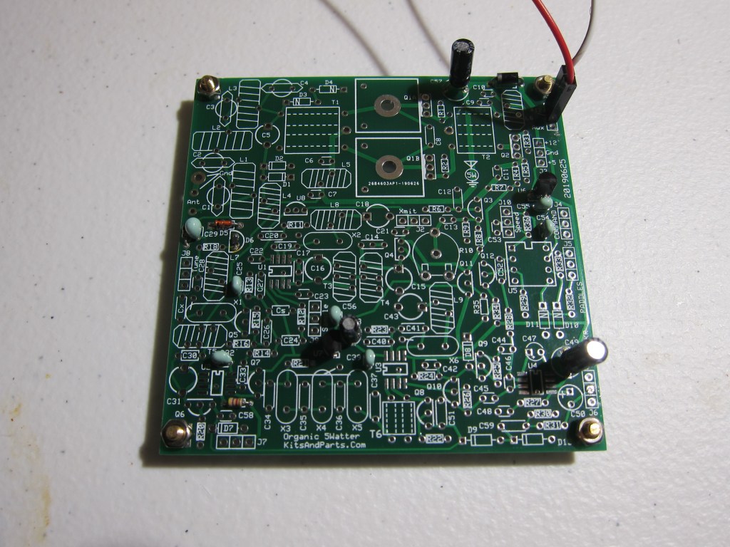
5W17 Phase 1 Complete 
5W17 Schematic Notes
Testing and Notes
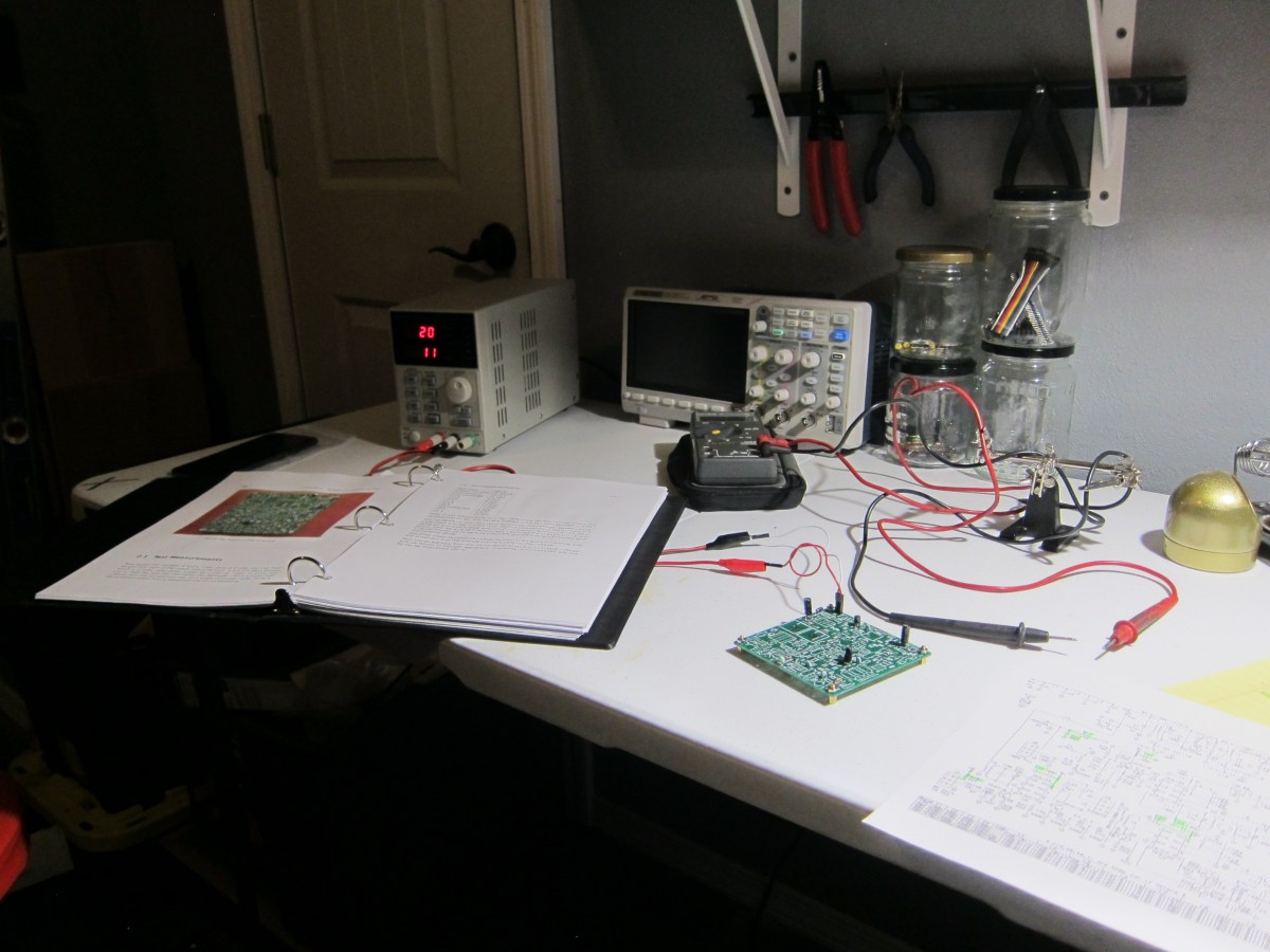
At the end of each section, K7QO gives a methodology for how to test the circuit which has been soldered into place. I’m glad that I have a benchtop variable power supply for this particular step because it made it easy to match the voltage that K7QO had in the manual: 13.21 VDC.
After setting my supply for this value and verifying it with my multimeter, I went to work taking measurements.
| Test Point | WB0ISG Value | K7QO Manual Value |
| Supply Current | 11 mA | 11.28 mA |
| D12 anode | 13.2 V | 13.21 V |
| D12 cathode | 12.92 V | 12.96 V |
| U3-8 (U3, pad 8) | 8.06 V | 8.00 V |
| U2-8 | 8.06 V | 8.00 V |
| J7-1 | 8.06 V | 7.96 V |
| U4-6 | 12.92 V | 12.96 V |
| J8-1 | 10.02 V | 10.05 V |
| Q5 collector | 8.06 V | 8.00 V |
| J3-3 | 4.99 V | 4.97 V |
| J3-1 | 12.92 V | 12.96 V |
Thankfully, my values are spot on for what K7QO had whenever he built his 5Watter. I’m confident that I have a properly working circuit thus far.
This method of building in stages is an education, for sure. By placing these components down in this particular order, I get to discover why these components are necessary to a properly functioning radio. Beforehand, I was just gluing baubles to a board and hoping it worked. I haven’t had this much fun in radio in a while!
