This particular block should be straightforward. Basically, Diz’s kit ships with a programmed IC for using with a paddle. I believe that we will also be installing the keying switching transistors as well in this section.
Components
- J4 – command button
- J5 – paddle jack
- J10 – speed control potentiometer (10k linear recommended; not included)
- R28 – 1M
- R29 – 10K
- R32, 33 – 470
- R34, 35 – 4.7K
- R36 – 470 (not installed; optional if no speed control pot is used)
- C21, 22, 53 – 100nF
- C52 – 33pF
- D10, 11 – NPC-127
- Q11 – 2N3906 PNP
- Q12 – 2N7000 JFET
- U8 – 8 pin header and ATTiny45 programmable IC (the keyer)
Circuit Explanation
The ATTiny series of programmable ICs have long fascinated me. I won’t get in too deeply into these because I’m focused more on understanding the physical componentry of radios for this series of articles. In a sense, I’m trying to see an entire forest, so I have to ignore certain trees for the time being. In the future, I might go into how programs are written for these. If you’re interested in this aspect of the hobby, I’d look at books by Jack Purdum W8TEE. He’s a knowledgeable and friendly author, lecturer, and ham who has helped me on a few occasions in the QRP-ARCI groups.io.
The circuitry surrounding component U5 (the ATTiny45 IC), which has been programmed for keying, is straightforward. There are four inputs: speed (pin 1), dit (pin 5), dah (pin 6), and command (pin 7). There are two outputs: tone (pin 2) and key (pin 3).
U6 (78L05), which was placed during Phase 1, feeds voltage into the ATTiny45 via both pins 1 and 8. Pin 1 is connected to both J10, which accommodates a 10K ohm linear potentiometer, and R36 (470 ohm) which is placed if no potentiometer is placed at J10. I put a trim pot at J10 because I wanted speed control. R36 was left empty. C53 (100nF) filters the voltage into pin 1, just as C54 (100nF) does for pin 8 when it was placed during Phase 1.
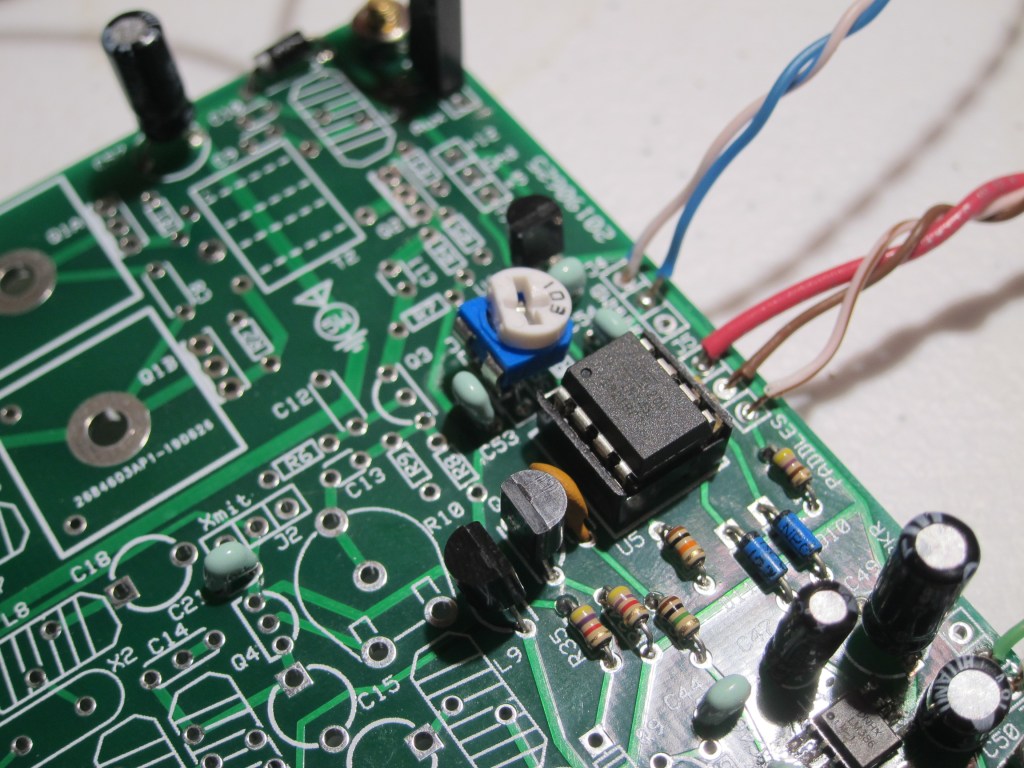
ATTiny 45 Keyer in situ 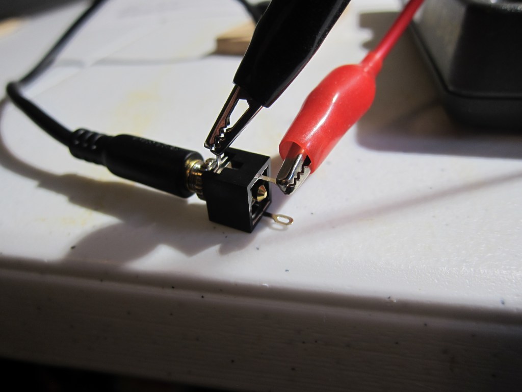
Checking headphone tip/ring/sleeve connections
Transistors allow small voltages and currents to control larger voltages and currents, which is the purpose of Q11 (2N3906) and Q12 (2N7000) in the keying relay circuitry.
Understanding transistors could be a series of articles all by itself. To understand this part of the circuit, I first had to understand the difference between PNP and NPN transistors, two types of Bipolar Junction Transistors (BJT). Then, I needed to know the difference between BJTs and Field Effect Transistors (FET). And of course, there are two types of FETs that are commonly used, depletion mode and enhancement mode FETs.
Basically, Q12 is an N channel enhancement mode FET. Enhancement mode means that it is off until it detects a signal, in this case from U5 pin 3 (ATTiny45 keyer). When it detects a signal, it then sends signals to two places: Q11 to switch on the transmitter and Q9/Q10 to mute the receiver.
Q11(2N3906), a PNP transistor, switches on to power the transmitter.
Q12 also sends a signal to Q9 and Q10 (J113) which mute the receiver. I’m getting ahead of myself here, but Q9 and Q10 are N channel depletion mode FETs which means they are on (passing signal from the receiver) until a signal is detected, which is sent from Q12 in this case. When a signal is detected (key down), Q9 and Q10 turn off.
Suffice it to say that to really understand what is going on here, I will need to experiment on my own with all of these transistor types.
Finally, another voltage regulator U8 (78L08) feeds the transmitter signal chain, starting with U1 (NE612A). C21 (100nF) provides stability while C22 (100nF) provides filtering.
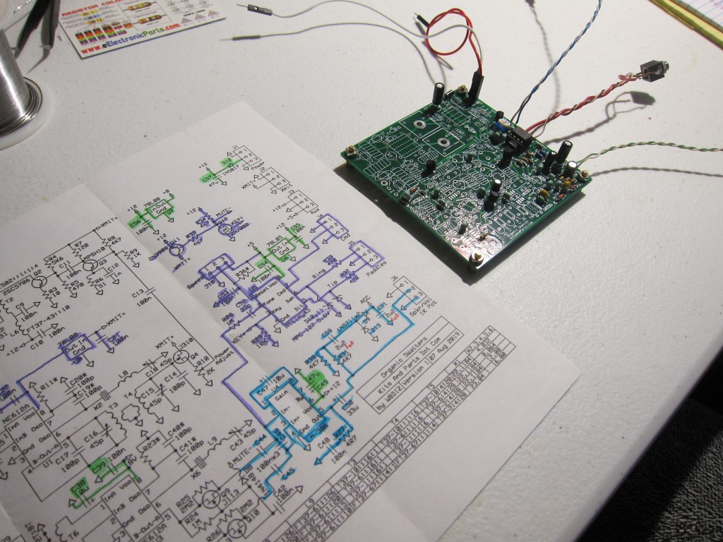
Testing
I followed my usual process of hooking up the battery leads to the bench power supply then poking and prodding the circuit on the appropriate traces. When I fired it up this time, it didn’t perform as expected. The voltage readout on the supply started out at 13.25 nominal, then wouldn’t reach that as I powered the circuit. Nor did the radio send the proper “OK” through the speakers. Odd… so I checked the voltage regulators…all good…and checked the voltage pins on the ICs…also good. I turned it off and then back on, but still nothing.
Then it occurred to me that the power supply current limiter was set to 20mA. I rolled it up to 30mA and sure enough, the voltage reached 13.25V with no issue. There simply wasn’t enough current to get it to work properly.
I turned it off and on again and this time, the radio sent out an “OK” in Morse. I touched the dit and dah sides of the paddle and they were correct. The speed pot that I installed also changed the speed from something below 5 WPM to something above 40 WPM.
The command button was also tested. When depressed, it sends “R”, then you key the desired command. Sending “X” sends out “R” then a steady tuning signal which will continue until you hit either dit or dah on the paddle. When unkeyed, pad 8 for U1 read 0V, as it should have. When keyed, the voltage read 8.05V, also within spec. In tuning mode, the amperage read 25mA.
I’m glad that there was nothing wrong with the circuit. I was worried at first, but as usual, it is user error that accounts for the vast majority of issues. Next up, I will be building the Beat Frequency Oscillator, or BFO.

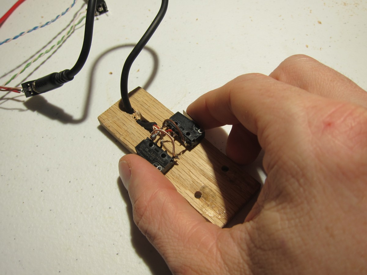
Two switches glued to a 1in wide oak board. 
A nice portable size.
